
Coverage of the 2 meter beacon is similar, but less expansive than that of the 6 meter beacon.
Click on the picture for a viewable (450k+) version, or here for a non-JPG version (1Meg+) (Sorry, but these are large, detailed images.)
Predicted coverage
of
the 6 meter beacon with no "enhancement":
|
Owing to the location of the beacon, the transmitter power, and antenna, this beacon has very good coverage over the state of Utah. It has been reported to be audible over most of the center of the state.
This map takes into account the majority of effects that affect signal propagation such as terrain, climate, and operating frequency. The map also has cities, highways, and relief-type terrain features embedded on it. The receive antenna is assumed to be isotropic at about 6 feet off the ground.
Note that this map assumes that no "enhancement" is occurring. That is, there are no meteor scatter, Es, Aurora, or any other sorts of "unusual" propagation events in effect.
About the antennas:
We are fully aware that most VHF/UHF weak signal operators primarily use horizontal polarization
The 6 Meter antenna - A simple J-pole, until September 2015:
For many years the antenna for the 6 meter beacon was nothing special: It is simply a J-pole. This antenna was vertically polarized and exhibited a gain (in free space) that is the same as a dipole (theoretically, 2.1 dBi.) The main reason that this vertically-polarized antenna was used for the beacon was that it was already available on-site. While this made the radiated signal cross-polarized with most operators' receive antennas, it should be kept in mind that a signal that is propagated by ionospheric reflection modes (E-Skip, Meteor Scatter, Aurora - just to name a few) will often have its polarization more-or-less randomized (shifted to horizontal, vertical, or something in between) so the polarity of either antenna becomes less important. This cross-polarization "loss" effect still can be dominant on signals propagated over land, however.
The 2 Meter antenna - A Cycloid Dipole:
For the 2 meter beacon we started out with a J-Pole, but we are currently using a 2 meter antenna that is Circularly Polarized (abbreviated CP.)
Why Circular Polarization? As mentioned before, most VHF/UHF weak signal work is done using Horizontal polarization. Obviously, receiving a vertically-polarized signal on a horizontally polarized antenna will cause an apparent increase in path loss, weakening the signal by 20dB or so.
The results of months of on-the-air testing:
This antenna was "temporarily" installed in early fall of 2001. As can be seen from the picture on the main beacon page, it is mounted on the eve-end of the roof on a piece of stout PVC pipe. As you can also see from the picture, a piece of clear plastic (1/4" thick Lexan (tm)) has been formed to shield the "trombone" matching network from accumulation of snow and ice.
Over the winter, the beacon was heard numerous times in Northern California via Meteor Scatter. There was also no indication (from afar) that the antenna was ever adversely affected by snow or ice accumulation (but no VSWR readings were taken, either...) While we have yet to find someone with switchable circular polarization analyze the signal, we have had a local amateur with a "polarization rotator" (that is, a rotator that will physically move the antenna between horizontal and vertical polarization) listen to the beacon - and he can tell no difference in signal strength as the polarization is shifted. It is worth noting that this person is receiving the signal via a path with multiple knife-edges and bounces.
The 6 Meter antenna now - also A Cycloid Dipole:
After September 19,2015 the 6 meter J-pole used by the beacon was replaced with a Cycloid Dipole - a "big brother" of the one that has been used on the 2 meter beacon since 2001. As it turned out, this antenna was originally constructed shortly after the 2 meter antenna, but it was never fully completed, partly owing to practical difficulties owing to its mechanical strength: It was so large and heavy that, unlike its smaller, 2-meter version, it could not support itself. Finally, after the J-pole antenna seemed to have failed the 6-meter Cycloid was completed and installed: It was at that point that we discovered that the J-pole had not actually failed, but rather that the shield of the Heliax (tm) had fractured and opened at the connector due to vibration and subsequent "work hardening" of the copper jacket .
If you want more information about this antenna, go to the Cycloid Dipole page, or you may send an email using the link at the bottom of the page.
Beacon parameter measurements:
It is interesting to remotely measure the various parameters of the beacon's operation to see what is happening. While it is not practical to get an extrememly accurate measurement of the power output of the beacon from a distance, there are two things that can be very accurately measured remotely: Carrier frequency and power ratios of the 100, 10 and 1 watt test carriers.
Frequency measurement:
Frequency is measured using a Wavetek 4031 communication test set locked to a GPS reference. A modulated carrier is generated 1 KHz below the beacon frequency and the frequency of modulation is then varied until the first sideband is zero beat with the carrier. This method is done because the '4031 can tune its RF carrier in only 100 Hz steps, but it can synthesize an audio frequency in 0.1 Hz steps.
The beacons' signals are then received using an SSB receiver and the audio output is fed into the sound card of a computer running Spectran - a program by I2PHD and IK2CZL - two Italian amateur radio operators. With this program, frequency steps of smaller than 0.1 Hz can be easily visualized, allowing "netting" of the '4031's output precisely.
With the '4031 locked to a known-good GPS reference, the frequency measurement uncertainty is no larger than 0.1 Hz at most. Due to propagation effects, the actual off-air uncertainty may be +-2 Hz or so in the short term, but using long term measurement techniques the accuracy should be better than 0.5 Hz.
The 6 and 2 meter beacons' frequencies are controlled by temperature-compensated quartz oscillators - but their specification is to be no more accurate than approximately 5 parts-per-million. Most of this frequency uncertainty is a result of temperature variations - but since the ambient temperature of the room in which the beacons are located is stable (being an underground room with cement walls and floors) and may be measured remotely (via the weather station) one can qualify the remote frequency measurements in that manner. Until 11/2006, the 70cm beacon used an Icom IC-490A allmode radio on the main floor of the cabin, so it's temperature varied quite a bit. Now, the 70cm beacon is co-located with the 6 and 2 meter beacons.
The following table shows the measured beacon frequencies on various
dates, along with the reported room temperatures.
|
Freq. |
(71.7 deg F) |
(75.0 deg F) |
(77.8 deg F) |
(72.0 deg F) |
4/26/2006 (64.7 deg F) |
11/25/2006 (66.6 deg F) |
4/17/2007 (62.1 deg F) |
| 50.070 MHz |
(-10.3 Hz) |
(-31.8 Hz) |
(-50.5 Hz) |
(-66.7 Hz) |
50.0699574 (-42.6 Hz) |
50.0699418 (-51.2 Hz) |
50.069959 (-41.0Hz) |
| 144.299 MHz |
(-8.1 Hz) |
(+42.3 Hz) |
(+37.3 Hz) |
(+10.7 Hz) |
144.2988884 (-111.6 Hz) |
144.2989842 (-15.8 Hz) |
144.2989794 (-20.2 Hz) |
| 432.399 MHz |
|
(-86.1 Hz@37F) |
(+629.1 Hz@52.7F) |
yet installed |
432.3994526 (+452.6) |
432.398909 (-91 Hz) |
432.39885 (-150.0Hz) |
Comment on the 70cm beacon frequency (after 11/25/06):
Power ratio measurement:
Another parameter that may be measured remotely is the accuracy of
the
10 dB power steps relative to each other. The following
table
shows the results of these measurements. The column under the
date
shows the measured power levels with respect to the 100 watt
level.
Ideally these should be -10.0 dB for the 10 watt power level
and
-20.0 dB for the 1 watt power level.
|
|
|
|
4/01/2004 | 12/05/2004 | 4/26/2006 |
11/25/2006 |
4/17/07 |
| 6 Meter Beacon 50.070 MHz |
-9.4 dB -19.9 dB |
-10.1 dB -19.8 dB |
-10.7 dB -20.8 dB |
-9.9 dB -18.5 dB |
-10.3 dB -19.6 dB |
-10.2 dB -21.0 dB |
-10.6dB -19.2dB |
| 2 Meter 144.299 MHz |
-9.5 dB -19.8 dB |
-9.5 dB -19.6 dB |
-9.7 dB -19.9 dB |
-10.2 dB -20.5 dB |
-9.5 dB -20.9 dB |
-9.6 dB -19.6 dB |
-9.9dB -20.6dB |
| 70 cm 432.399 MHz |
n/a |
n/a |
n/a |
n/a |
n/a |
-10.4 dB -20.2 dB |
-10.5dB -20.0dB |
These readings are probably accurate to within a few 10ths of a dB or so. Remember that it isn't the absolute power level that we are interested in (because we really can't tell exactly how much power is being radiated in all directions - as that depends upon the antenna and, at a distance, propagation and terrain) but it's the difference between power steps that interests us. Practically speaking, if the power levels are within 1dB of where we think they are, we are happy...
This measurement may also be done using Spectran. The beacon's signal is tuned in and displayed on Spectran. One may then observe the relative power ratios of the audio signal - which correlate exactly with the RF levels - if you do it right.
For this type of measurement to be valid, one must either turn the
receiver's
AGC OFF or one must attenuate the signal such that it does not
operate the AGC at all! Also, for the signal level measurements
to
be accurate, one must have a reasonable detected signal/noise ratio of
the signal. With Spectran this is accomplished simply by
selecting
a narrow-enough detection bandwidth to do the job. I used a
bandwidth
of 0.34 Hz, as that was wide enough to be able to accurately track and
respond to the 5 second test carrier while provide more than enough
signal/noise
ratio for a good measurement even at the 1 watt carrier level.
Technical Info about
the beacon transmitters:
All three beacons are based on GE Master Exec II VHF transceivers with the 2 and 6 meter beacons having 110 watt power amplifiers and the 70cm beacon having a 75 watt power amplifier. The receivers were removed (as they were not needed in this project) and the transmitters were re-crystalled and tuned for the new frequencies. Most of these modifications/designs were done by Clint, KA7OEI and are similar for both radios.
The description below describes the modifications required for
the 6 meter beacon. A few minor changes were done to accommodate
differences in the 2 meter and 70cm transmitters' circuitry and are
noted as
appropriate.
 |
As designed, the radio does not lend itself to precise and repeatable power adjustment - at least not at any power level below 50 watts or so. One of the design goals for this beacon was to provide a test carrier at the 100, 10, and 1 watt levels - a 20 dB (100:1) range, as set by the controller.
To accomplish this, the original power control circuit was disconnected and the predriver's pass transistor (Q217 - an NPN) was replaced with a PNP darlington The power control on this transmitter operates by varying the supply voltage to the predriver stage on the PA deck, which is done by varying the base current to the PNP darlington. Since this transmitter is class-C, the operating point is very critical and temperature sensitive: Setting the output power based on predriver voltage alone would result in a thermally unstable power setting.
To get around this, a piece of PTFE insulated wire was laid atop a portion of the stripline at the PA output (just before it entered the lowpass filter) to couple a small amount of RF energy. This energy was rectified, yielding a voltage based on the power output.
With this voltage, a closed-loop "servo" power control could be established: If the voltage from the RF detector was too high, the voltage applied to the predriver stage could be reduced and if the voltage from the RF detector was too low, the predriver voltage could be increased.
To set the higher (10 and 100 watt) power levels, the voltage from
the
RF detector was "swamped" by a lower resistance placed between the RF
detector
output circuit and ground that is switched in and out by a power
FET.
When the resistance is switched in, the output voltage of the detector
is dragged down to a lower value and the servo loop increases the power
to compensate. Two FETs and potentiometers were implemented to
provide
separate adjustments for the 10 and 100 watt power levels: The 1
watt level is set by an "unswamped" voltage from the detector (i.e.
maximum
sensitivity.)
 |
[For the 6 meter beacon only, selectable attenuation was added between the predriver and the driver stages. When at the 10 and 1 watt power levels, this attenuation is present, but when running at the 100 watt power level, the attenuation is switched out using the T/R relay that was removed from the PA deck. The relay is energized when the 100 watt power level is selected. (Note: The 2 meter power amplifier chain has enough dynamic range and is stable enough over the 20dB range to not require this "extra" circuit.)]
Providing clean CW keying was another problem to overcome: The normal PTT line for the radio could not be used because doing so would not only produce a somewhat "chirpy" note (from the oscillator being powered on and off) but the "attack" and "decay" of the keyed carrier was very abrupt, resulting in very "clicky" keying.
The solution was to key by "fooling" the RF power control circuitry: If an external voltage is applied to the RF detector exceeding that set by the servo threshold, the power controller will "think" that the output power is too high. It will dutifully try to reduce power - but since the input voltage is "artificially" high, it will reduce the power all the way to zero. By "shaping" this external voltage, a good keying waveform could be obtained.
Keying in this manner also solved another potential problem:
If
the RF input were keyed, the power control servo loop would have
detected
a "low RF power" state and tried to turn the power all the way up when
the radio was unkeyed. This would result in a "click" when the RF
input was keyed as the power started out very high, and was then
throttled
back to the desired level.
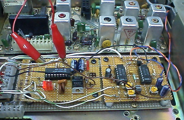 |
The entire beacon is controlled by a PIC microcontroller (a PIC16C84) programmed with the beacon text and the appropriate routines to produce the text and power level test carriers. An additional "feature" was programmed so that if the primary (AC) power to the beacon failed, it would operate only at the 10 watt level (omitting any 100 watt transmissions) and conserve power if the beacon is connected to a backup battery.
Because an antenna with greater than unity gain is used, the actual
RF output power from the transmitter is less than the
radiated
power. For example, if the stated power is EIRP (Effective
Radiated
Isotropic
Power)
the antenna gain (about 2.1 dBi) minus the coax loss allows a higher
EIRP
than the actual transmitter power. The stability of the beacon's
power control is about 1dB for each of the power levels.
70cm beacon:
For 70cm, some instability was noted in the PA as the power was
lowered below about 10 watts. This was tracked down to a mismatch
between the output impedance of the driver stage and input of the final
amplifier stage: The strategic addition a small capacitor and
coil and the removal of an existing capacitor completely tamed the
problem. Note: The final amplifer used in this radio is
the "60 watt" version using 2 transistor and the small circuit board
overlaying an older 4-transistor amplifier board. It is likely
that not all versions of the final amplifier are so-affected.
The "RF Sense" line (a piece of wire paralleling the PC board stripline) is similar to that of the 6 and 2 meter beacons. It was noted, however, that these circuit board traces got quite warm at the high power level, owing to resistive losses. For this reason, the diode sense circuit was located a few inches away from the pickup line, connected with a short run of small-diameter coax. It was also noted that at high power levels, the single 1N914 diode being used to rectify the RF was getting quite hot, causing the rectified voltage to go down as the diode heated up, causing a commensurate increase in the RF power output. This was partially mitigated by reducing the coupling slightly by moving the coupling wire a little bit away from the stripline, but it was necessary to maintain relatively tight coupling in order to get enough DC voltage from the circuit when operating at the 1 watt level: For proper keying, there must be adequate DC voltage obtained even with an RF output power level of just 100 milliwatts. In order to better-tolerate the high power levels, several 1N914 diodes were put in parallel (to ground) to increase the power-handling capability and the problem was solved.
"Mho, mho, tell me mho!!!"
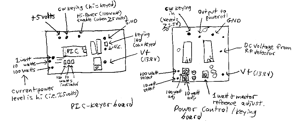
Do you want more information about the modifications? A few scanned hand-drawn diagrams are available detailing some of the changes/modifications required to make a beacon out of this Mastr II. These documents describe the 6 meter beacon's modifications. For specific information on the 2 meter or 70cm beacon, send an email to the address below.
NOTE: The drawings below are hand-drawn and
then
scanned - sorry! You will not likely be able to
print
all of these image out directly from your browser because of the size
of
their bitmap - you will probably have to save them to disk and then
print
using another program. Please note component value changes
in the text below. These images are:
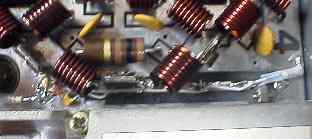
The PA Deck circuit modifications:
Note: Understanding this drawing requires documentation showing component location of the GE PA board itself, as specific components are directly referenced.
As pictured above, there is a stripline connection between the output of the PA itself and the lowpass filter (located under the die-cast shield.) Small pieces of wire were used to secure the small piece of PTFE wire (removed from some high-end CAT5 computer networking cable) to the stripline. The picture does not show the inductor/potentiometer depicted in the schematic, as that was a later modification. The potentiometer may be replaced with a fixed resistor in the 180-200 ohm range.
Important: At the low power setting, adjust the coupling so that there is between 1.25 and 1.5 volts coming out of the RF detector. This coupling may be adjusted simply to moving the insulated coupling wire closer/farther from the circuit board stripline from which the energy is coupled. If there is too much voltage, the beacon will not fully "un-key" at one or more power levels due to the excessive output from the RF detector and the inability of the keying circuit to "fool" the servo into thinking that there is already too much RF output.
The original power control worked by varying the base voltage of an NPN pass transistor which, in turn, varied the voltage of the predriver stage. This NPN transistor (Q217) was removed and a PNP darlington (a TIP127) was installed in its place. Note that the emitter and collector have been swapped, and that the base no longer goes to the original location and the two resistors are soldered directly at the TIP127. It should be noted that the 1k resistor in series with the base and power control was later changed to 470 ohms. Also, the 2.2k on the emitter of the transistor connected to U1C was changed to 2k.
Original implementation - For the 6 meter beacon only: The switchable attenuator is shown on the right side of the drawing. Essentially, this consists of a 90 ohm 3 watt resistor (consisting, in this case, of 6 15 ohm resistors in series - that was all I could find...) and a 150 ohm resistor across R208. The original T/R relay from the PA deck was removed and the former transmit RF path through the relay was jumpered over (yes, it is a pain to do that as it requires un-mounting the circuit board and un-bolting the RF transistors. If you do this, it is strongly recommended that the old heat-sink grease be removed and fresh grease be applied...) and was configured as shown to "bypass" the 90 ohm resistor when the 100 watt mode was selected. Note the NPN relay driver transistor and associated components (diode, resistor, capacitor) were "dead bug" wired onto the (grounded) case of the relay.
Finally, a very simple modification showing the three control leads (the Power Control, the Power Detector, and the "100 watt enable" relay control - the latter not used on the 2 meter version) and that they are RF bypassed. This was done by drilling a hole in the wall of the receive compartment and bolting a solder lug (with three capacitors on it) into place. This prevents (as much) RF from being conducted to the control circuits as well as out of the radio on power/control leads.
UPDATE 10/12/03 - A Slight redesign of the 6 meter beacon's power control circuity:
Additional modification information: Due to a failure in the 6 meter PA board, the entire module was replaced. At the time of replacement, further modifications were made to the PA Board's power control. These are as follows:
The GE PA deck uses class-C amplifiers throughout. This amplifier topology is very non-linear and at the low end of the curve - just above "cutoff" - a very small increase in drive power will cause a very large increase in output power. What this means for the power control servo is that at low power levels, the loop gain will be much higher than at higher power levels. This higher loop gain can also lead to instabilities.
Power is controlled by adjusting the amount of supply voltage on the prediver stage. Typically, for 100 watts of output, only about 6.5 volts is needed on the predriver for this output, while only about 1.85 volts is needed for 10 watts output and 1.65 volts is needed for the 1 watt output - with all output disappearing only a few millivolts below that required for 1 watt output.
Originally, the T/R relay was used to switch attenuation in/out of the RF path between the predriver and driver stages so that 1 and 10 watt power levels would be moved "up" onto voltage/output power curve to a point were it wasn't as steep. Also, the original circuit used a PNP bipolar transistor and simply controlled the base current. With the PNP transistor, one was also faced with the problem of the gain being higher at lower currents (that is, low power) than at higher currents - a problem that further exacerbated the situation.
In the rebuilt circuit, a P-channel power MOSFET was used with the original power control circuit. The MOSFET, unlike the PNP, is a voltage-controlled device and is somewhat more linear - especially at the low-current end of the world. This helped to reduce the "steepness" of the curve even more.
Finally, on the rebuilt circuit, the gain of the PA section was reduced somewhat. It was noted that increasing the predriver's supply voltage from 6.5 volts to full supply voltage of 13.6 volts only increased the power from 100 to 130 watts - so much of the control range was wasted in that manner. Reconfiguring the 1.2 ohm series resistors on the base of the driver stage reduced the gain such that, when cold, full supply voltage on the predriver (13.6 volts) produced about 100 watts. At our target output power of 70 watts (with antenna gain, that provides our 100 watts EIRP) the predirver's voltage was about 10 volts or so. At 10 watts, there needed to be about 4.5 volts, and 1 watt of output required about 3.5 volts on the predriver's collector.
With these modifications, the loop gain in the servo was greatly reduced at the lower power levels. If there is servo instability, one will observe spurious amplitude modulation of the output power when the output is reduced to very low power levels when in the 1 watt mode. After modification, power could be adjusted down to 20-30 milliwatts of output with no instability - something that could never be done before.
Notes:
The Power Control Circuit:
This circuit works by taking a voltage from an RF detector (described above) and using it in a closed-loop feedback circuit to dynamically adjust the power. The voltage output by the detector pictured was about 1.25-1.5 volts or so at 1 watt. To get higher power levels, two MOSFETs are used to "shunt" some of the current from the RF detector: When 100 watts is selected, the MOSFET "shorts" the bottom end of the 2k pot to ground, reducing the effective sensitivity. Likewise, if 10 watts is selected, the bottom of the 5k pot is grounded and that is adjusted for the desired output power. If none of the MOSFETs are turned on the detector operates unhindered and at maximum sensitivity. Reducing the effective sensitivity of the RF detector reduces the RF voltage, making the controller increase the output power to compensate.
The RF detector voltage is buffered by U1A and then "compared" (by U1D) with a reference voltage generated by a 5 volt regulator, the buffered output of the 50k pot and U2A. If the input voltage is above the reference, the output of U1D goes low, and vice-versa. This voltage is then sent to U1C, an adjustable current sink: The more voltage there is on pin 6, the more U1C ties to increase the base voltage on the 2N3904 transistor, which makes the transistor conduct more current, and more current is pulled from the "Power Control" line. Note the 0.22 microfarad capacitor on the keying line: This is used to limit the slew rate of the power control, and this reduces the rise/fall time of the keying, reducing key clicks and low level audio-frequency noise from the power control circuit.
Keying is accomplished by using U2B as a comparator. The input voltage is compared with the reference voltage from U2A (it was a handy threshold voltage, so why not use it?) and if the input voltage is low (i.e. unkeyed) then the output of U2B is high, and vice-versa. U2D is outputting the reference voltage and provides a "reference" of the required keying voltage. The output of U2B is applied (through the 2.2k resistor) to the output of U2D - except that the resistor limits the current, and the diodes prevent the voltage from being dragged too far away from U2D's output voltage (i.e. about 0.6 volts in one direction and 1.2 volts in the other.) The "limited" keying voltage is applied to U2C (a buffer) and a 0.47 microfarad and the 220k resistor and 22k/diode combination set a time constant, which helps shape the keying waveform. The 220k resistor and 22k/diode form a "dual" time constant.
The output of U2C is applied (via a diode) to the RF power detector input. When the transmitter is unkeyed the output of U2C is a volt or so higher than the reference voltage (because of that odd diode arrangement, remember?) and the power control "thinks" that the output power is too high, so it reduces the output power... all the way to zero. When the transmitter is keyed, the output of U2C goes down below the reference voltage - and being coupled with a diode, is no longer affecting the power output.
Why that strange diode arrangement? Since the op amp operates from 12 volts, if the "swing" into U2C weren't limited to be close to the reference voltage, the keying waveform would be non-symmetrical: U2C could go all the way to the supply voltage and when the radio was keyed, the capacitor would have to discharge all of the way from 12 volts down to 2 volts or so before the radio would key up. When unkeyed, it would have to go from 0 volts to just above 2 volts or so. This would clearly make the "key down" faster than the "key up" and hence the "strange" voltage limiting and dual time-constant stuff.
Although the pin connections are not shown on the schematic, both U1 and U2 are powered from the V+ (12 volt) radio supply.
The Beacon Controller:
The beacon controller currently uses a PIC16F84 and the real
work is done
by
the software inside (which will be posted later if there is
interest.
If you are interested in the software now, send an email to WA7X using
the link below and it will be passed on to Clint.) If you
are interested in the source code for the beacon controller, please
note that unless you have the C compiler that I used, it may not be of
much use. Similarly, a .HEX file can be made available, but
unless you have a means to program the processor it, too, will not be
of much use, either.
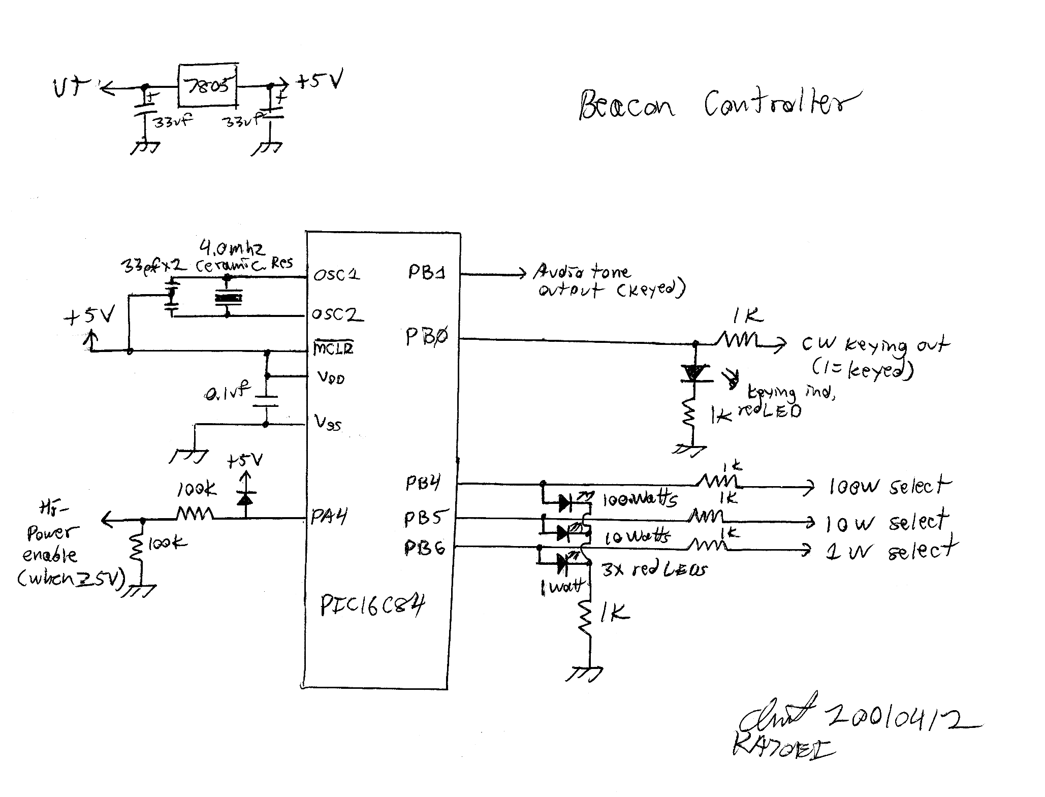
The PIC is clocked using a 4 MHz ceramic resonator: The clock frequency isn't critical (as it affects only the sending speed) and the resonator was cheap and abundant.
A 7805 regulator provides the supply voltage. Various LEDs are used to indicate the operational state of the processor Note that PB1 (go the Microchip web site to get a data sheet on the 16F84 to get the pin numbers...) provides an audio tone output and could be connected to a small speaker (through a 100 ohm resistor and 10 uf cap) or piezo sounder, or even used if MCW (modulated CW) was required for some reason. PB0 provides a DC level for keying with the "1" state (about 5 volts) being the "key down" condition.
The PA4 input is used to detect whether or not the beacon was to operate at 100 watts. If this pin is pulled to 5 volts or higher, the beacon cycle will use the 100 watt power level. If it is left floating or pulled low, only 10 watts (maximum) will be used. The intent here is to tie this line to the output of a DC power supply (such as a filtered DC "wall wart") and if the power were to fail, the voltage would go away and the beacon would revert to the 10 watt power level, thus conserving batteries. Provisions for a low voltage battery disconnect (to prevent a complete flattening of the battery...) were going to be done elsewhere.
All beacons are connected in parallel with the outputs of the
controller,
so they are precisely "simulcast."
Comment: More recently, use of the PIC16F84 has
been supplanted by the use of
the PIC16F628, PIC16F819, or even the PIC16F88. These newer
devices have more
features, are less expensive, and identical pinout and have built-in
oscillators, completely eliminating the need
for a 4 MHz resonator or crystal at all.
Adjustment and calibration:
This procedure is applicable to both the 6 and 2 meter beacons.
Adjustment requires a wattmeter and is best done when connected to the antenna being used. Since the power detector does not use a directional coupler, the precise VSWR conditions will likely affect the output power somewhat. Generally, the forward power will drop in the presence of a high VSWR because the RF detector will be detecting the reflected power as well as the forward power.
When adjusting the power, it must be remembered that everything is calibrated from the "1 watt" reference control, and power is thus set at this power level. The calibration procedure is as follows:
If you wish to contact the operator of this beacon with a question you may send an email to WA7X.
Go back to the main WA7X Beacon Page
Also at this site:
For more information about 6 and 2 meters, take a look at these pages: