Click on the picture for a larger version.
Are you interested in using a Cycloid Dipole for your own
purposes? If so, please read
this.
|
The 2 Meter antenna - A Cycloid Dipole:
For the 2 meter beacon we started using a 2 meter J-pole - but in a service where most people listening were likely to be using horizontally polarized antennas, this was not considered to be ideal.
Because a good, horizontally-polarized, omnidirectional
antenna is
rather
difficult to construct, we held off on doing so. In the
meantime,
we found an antenna that offered Circular Polarization (CP).
Considering that with this mode of polarization that it is unlikely
that propagation conditions may be encountered that would make the
circularly-polarized signal favor either
a horizontally or vertically
polarized antenna, we
decided that it would offer the best of both worlds.
The downside? Circular Polarization, when received on a linearly-polarized antenna (i.e. vertical or horizontal), will typically suffer an apparent 3db decrease in signal - but this is a lot less than one might experience under cross-polarized (that is, a vertical transmit signal on a horizontal receive antenna) conditions. The thought is that with the propagated polarization being somewhat randomized, at least some of the "fade" that one experiences when using linearly-polarized antennas on each end of the path is likely to be due to cross-polarization loss - and this effect is circumvented with the use of CP.
A 6 Meter Cycloid Dipole:
Although the companion 6-meter Cycloid Dipole was constructed soon after the 2 meter version in about 2001, it was never fully completed, laying around and developing a nice, dark patina. The reasons that it languished for so long had to do with the fact that the J-pole was working just fine and that after it was constructed, the 6-meter antenna with its 1/2" diameter copper water pipe was not strong enough to properly support itself like the 2 meter version and would this require additional structural support.
In 2015 it was noticed that the 6 meter beacon's signal had dropped off by several S-units and subsequent investigation revealed that the measured VSWR at the transmitter was on the order of 5:1 and that the reduction in signal strength was not only due to the loss of efficiency, but also due to the fact that the power control servo circuit in the beacon itself was detecting this reflected energy as transmitted energy and dutifully reducing the transmitter output power. A further investigation showed that there was infinite DC resistance across the antenna terminals - which should not have been the case for a J-pole! Because signal was being radiated it was naturally assumed that the ground (shield) side of the feed coax had broken loose somewhere. Since the beacon had likely been operating in that state for several months by the time we'd discovered it, we simply left it alone for the time-being and set about finishing the construction of the 6 meter Cycloid.
The Cycloid Dipole
antenna:
The CP antennas that we are testing are Cycloid Dipoles constructed of 1/2" rigid copper tubing (See photos, below) with each one being constructed similarly. While it may not be obvious from the picture, the antenna itself (the part on the far left) is fed with a balanced line/matching network consisting of parallel 1/2" copper tubing. Most of the structure (from the part where the "balanced line" begins and everything to the right of it) is just the matching section - A stub-tuned 1/2 wavelength balanced line.
The advantage of the 1/2 wavelength stub-tuned line is that it can be used to match almost anything at all. The obvious disadvantage of it is its size: On 2 meters, you need about 2 meters (about 6 feet) of tubing just to construct a matching network. In our case, using a line constructed of large-diameter air-dielectric copper tubing made for a very low-loss matching network. It is possible to use lumped-constants (e.g. coils and capacitors) to effect a match - but these may be lossier and more "fragile" in terms of power handling capability. While we believe that we have come up with a somewhat "simpler" scheme to match the antenna, seeing how well the antenna has survived over time and through several winters has made us reconsider whether or not it would really be "better" or not.
At the bottom of the antenna on the far right (in the picture)
may
be
seen the 1/2 wave coax (not choke) 4:1 balun used to
transform
50
ohm unbalanced to 200 ohms balanced: The antenna could have
been
fed directly with 50 ohm coax at a different tap point (using a coax
"choke"
balun) but the 4:1 balun seemed to be much better-behaved and, unlike
the
50 ohm "choke balun" arrangement originally tried, completely
insensitive
to coax orientation - a good indication that the feedline is not
doing radiating of its own.
|
The term "cycloid" means "resembles a circle." The actual antenna, however, is clearly rectangular - so why the name? Ideally, the "horizontal" part of the antenna would be circular (see the drawing below) but anyone who has done any sort of construction that requires bending tubing already knows that without the proper tools and materials, making accurate, repeatable circular bends is extremely difficult. It is for this reason that a rectangular radiating element was used, constructed using simple straight sections and right-angle connectors. According to computer simulations, performance is no different from what it would be were it circular - provided that the antenna's proportions are re-sized appropriately.
|
If this antenna performs as predicted (in free space) it will have about 1.8 dBic (db gain above an "isotropic" circular antenna, or about -1.2 dBi. Remember that we will experience an apparent 3 db gain reduction when the receive antenna is linearly-polarized) and have an ellipticity ranging from 1.05 to 1.25 and be uniform in gain to within 0.5 db anywhere on the horizon. In real life, of course, performance will likely be somewhat worse - owing mostly to the fact that it cannot practically be mounted in free-space and there will inevitably be some effects from the matching network and feedline, but we can hope that it is somewhere in the ballpark.
The results of many, many months of on-the-air testing:
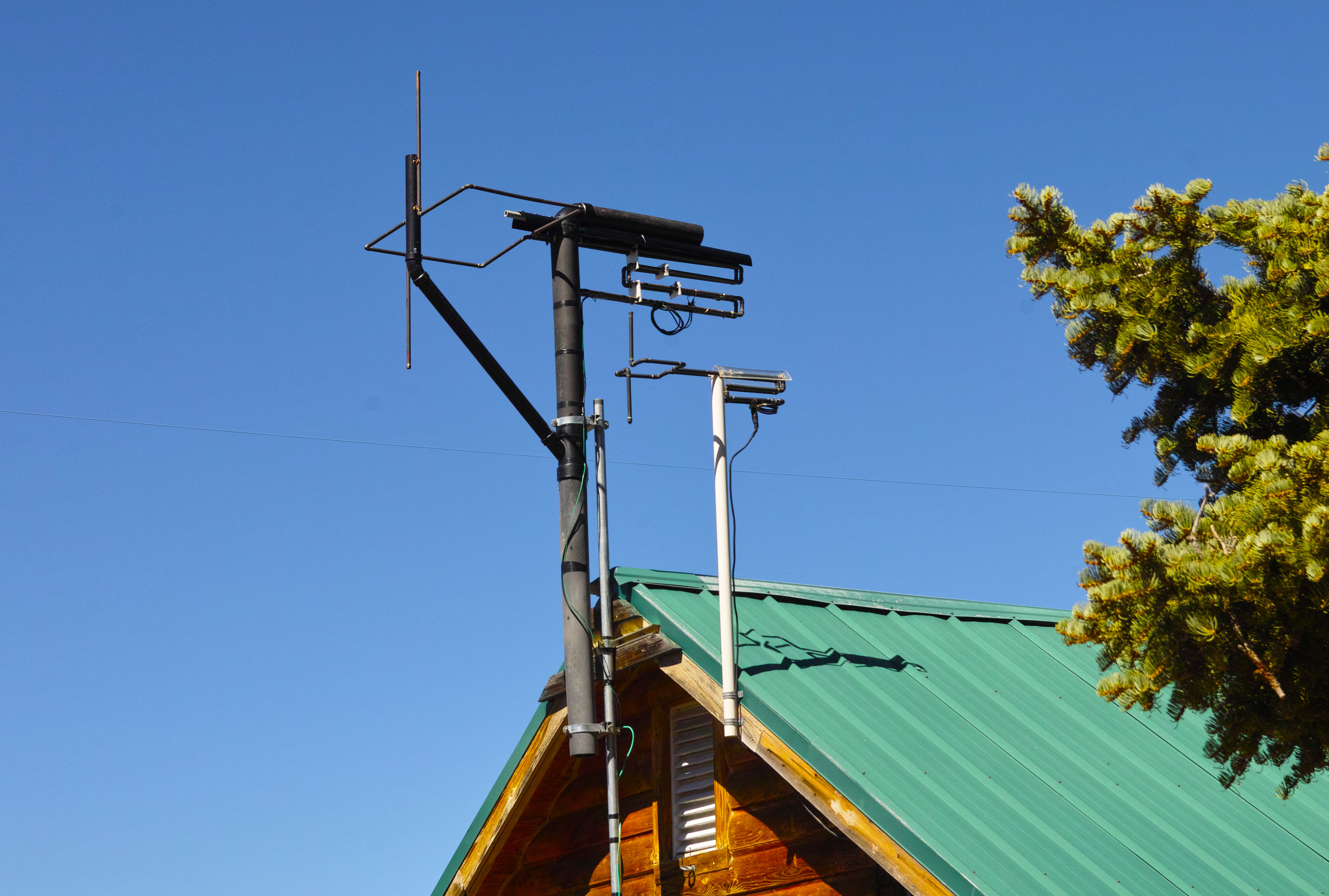
The 2 meter antenna was "temporarily" installed in early fall of 2001 and as of today, it is still in service. As can be seen from the picture below it is mounted on the eve-end of the roof on a piece of stout PVC pipe. As you can also see from the picture (see the one below) a piece of clear plastic (1/4" thick Lexan (tm)) has been formed to shield the "trombone" matching network from accumulation of snow and ice.
This "temporary" installation seems to have become more permanent, and over the years the beacon has been heard numerous times in Northern California via Meteor Scatter. There was also no indication (from afar) that the antenna was ever adversely affected by snow or ice accumulation (but no VSWR readings were taken, either...) While we have yet to find someone with switchable circular polarization analyze the signal, we have had an amateur with a "polarization rotator" (that is, a rotator that will physically move the antenna between horizontal and vertical polarization) listen to the beacon - and he can tell no difference in signal strength as the polarization is shifted. It is worth noting that this person is receiving the signal via a path with multiple knife-edges and bounces and at a distance of about air 75 miles.
The Design of these Cycloid Dipoles:
It is absolutely fair to say that the design of this antenna was inspired by commercially-available low/medium power FM broadcast antennas. This sort of antenna is somewhat well-known in the FM broadcasting world as a "Ring and Stub" design (a term used to describe ERI's antennas, for example.) A link containing pictures of some broadcast-band antennae - including a "ring and stub" may be found here - and if you are really interested, you can do an internet search and come up with a few more examples.
For obvious reasons alluded to previously (see the sidebar) it was decided that the "horizontal" portion of the antenna would be rectangular instead of round. So, from pictures of similar commercial antennas, a "rectangular" antenna was laid out using the approximate proportions of the "round" ones. Then, computer-aided antenna analysis was brought to bear.
The primary design tool was NEC-2, a program with a very long lineage and one that, when used in detail, requires a fast computer with a LOT of memory if one doesn't wish to spend eternity trying various configurations. Note: Using this program is very awkward and is far beyond the scope of this document - if you wish to obtain more information on NEC-2 or other antenna analysis software. One resource of information is WB6TPU's "unofficial" NEC Archive. Of course, one can also do an internet search. Note: I am not a "NEC" expert, so please do not ask me any questions about it.
Another useful antenna analysis program is Makoto Mori's MMANA
program. This program is based on the MININEC model and is
not
nearly
as powerful as the full-blown NEC variants (e.g. it doesn't "know"
about
circularly-polarized antennas.) However, it provides
excellent
agreement
to NEC in terms of radiation patterns and their horizontally and
vertically-polarized
components, as well as having a much easier-to-use graphical
interface.
In broad terms, if the radiation patterns of the horizontally and
vertically
polarized components are of the same magnitude, one can generally
be assured that the antenna is reasonably well-behaved in terms of the
circularity of its radiation.
 |
The evolution of the design:
As mentioned above, the first step in the design of the antenna was to obtain approximate physical proportions from an existing antenna design. Then, various simulations were done at varying frequencies to determine those frequencies at which the radiation from the antenna started to become both omnidirectional and circularly polarized. After trial and error, it was found that the "trial" antenna best exhibited the desired properties at around 31 MHz. (Note: There is no significance to that frequency - it just happens to be where the more-or-less random antenna size yielded the best properties.)
At this point a lot of experimentation was done with the proportions of the antenna elements - always keeping the antenna symmetrical. After experimenting (on computer) with various physical parameters for a while, one gets a "feel" for how different physical parameters affect the radiation pattern and the polarization properties - so eventually, a design was derived that, in simulation, had excellent properties (e.g. uniform omnidirectionality at the horizon, good axial ratio, etc.) The only problem was that this antenna was still in the 31 MHz area.
A linear rescaling of the antenna was done to put it at
approximately
50.1 MHz and it was immediately noted that this antenna design did not
lend itself to rescaling in that manner. Because of the
recent
experience,
having the "feel" for how the antenna's proportions affected its
performance
allowed relatively painless manual tweaking of dimensions.
The
antenna
was then scaled again (using prior experience - as well as the "feel")
to 144.3 MHz. You might ask "Why 144.3 and 50.1 MHz
instead
of
the FM band?" The answer is that this antenna was
being
designed
specifically
for use with the beacon.
The predicted
radiation
pattern:
The radiation pattern of the 6 meter version of the antenna, as predicted by the MMANA program is shown below. (Note: This antenna has been constructed and tested, but not "ruggedized" or installed.) As mentioned, MMANA does not "know" about circular polarization - but in testing with an antenna analysis that does know about it (NEC-2) it has been determined that, in general, there is good agreement between the two - as far as MMANA goes, anyway.
The plot shows the predicted antenna pattern for the 6 meter cycloid, the center of which being mounted 7 meters above a "real" ground (that is, not a perfect ground, but a "typical" lossy ground. The left-hand plot shows the horizontal pattern of the antenna (as if viewed from above) at the elevation of peak gain (11 degrees) while the right-hand plot shows the vertical pattern at an orientation corresponding with the peak gain. Note that, under these conditions, there is more energy in the vertical plane than in the horizontal plane, but that both fairly well-behaved omnidirectional patterns. It is also worth noting that at higher elevation angles, the "circularity" of the pattern predictably decreases, with only the "horizontal" energy remaining directly overhead.
In the real world, any antenna's pattern will be skewed by nearby objects - including the earth below, the mast supporting the antenna, and even the metal of the coax feeding the antenna. Typically, the gain will be somewhat reduced (especially in the vertical plane) in the direction of the mast and somewhat enhanced in the opposite direction - precisely the effect expected when side-mounting an antenna. Because the antenna must be mounted/connected to something this effect is unavoidable. As with pure vertical antennas, the effect becomes more dramatic as the spacing between the supporting mast and the antenna approaches 1/4 wavelength. Keep this in mind if you are trying to obtain either the best omni pattern - or if, in fact, you are intending to throw more gain in a particular direction!
A note about the feedpoint impedance: If you look at the pattern plot, note that the predicted feedpoint resistance is about 18 ohms resistive with the reactance being at about +J300 ohms. While this value hasn't been measured directly, we have measured the locations actual tap positions on the 1/2 wave matching network and have determined that, in fact, the empirically determined tap locations do correlate well with those numbers!
Now, you see why we are using a 1/2 wave "open wire" matching network!
A few more comments:
About the antenna
itself:
First of all, in the simplest sense, this antenna is nothing but a dipole bent into an odd shape. It is, however, not a 1/2-wave dipole! It is NOT resonant at the operating frequency at all. It does not have a feedpoint impedance anywhere near 50 ohms resistive (see above!)
How does it work, then? At the risk of gross oversimplification, here is a quick explanation:
If, using a balanced line, you feed a signal into two equal-sized and equal-length conductors that are not parallel to each other (i.e. not just more balanced line) then a signal will radiate from those added conductors. If they diverge from each in opposite directions, it begins to resemble what is commonly called a dipole. It just so-happens that when the total length of those two conductors is approximately 1/2 wavelength, the feedpoint impedance can come close enough to 50 ohms to be useful without requiring a matching network.
If these two elements are both lying horizontal,
then the
polarization
of the antenna is, in fact, horizontal. Likewise, if that
antenna
is rotated so that the two elements are vertical, then so is the
polarization.
If you were to put one element vertical and another element horizontal,
then some amount of signal would be radiated in the vertical plane, and
some would be radiated in the horizontal plane. In the case
of
the
half-wave horizontal dipole, it is important to note that signal is
radiated broadside
to the wire - but not off the
ends and therefore, the
horizontally-polarized half-wave dipole
is not an omnidirectional
antenna.
 |
 |
Now, what if you were to form that horizontal dipole into a ring - but not with the ends touching? Would it then be omnidirectional? The answer is: No, not quite. True, the nulls off the ends of the antenna will greatly diminish, but radiation in all directions will not be equal. Why? It is because not all "segments" of the wire of which the antenna is constructed will radiate equally. For instance, the segments of wire near the feedpoint will (for a 1/2 wave dipole) have a lot of current but relatively little voltage while the very ends of the dipole will have a lot of voltage but little current. The distribution of the current and voltage that have a marked effect on how much a particular "segment" of wire will be able to radiate.
If you were to alter the shape of that "ring" so that its aspect presented more of those segments of the wire that did little of their own radiating in directions that needed more signal - and that less of those segments that do more radiating were presented in those directions where there had been too much signal, then one could conceivably make the antenna present a pattern that was more omnidirectional in nature.
Another way to help achieve this goal is to change the fundamental current distribution of RF along the conductor, and one way that this can be done is to change the length of the conductors - but doing this also means that you will not likely end up with a nice match that is anywhere near 50 ohms, either. By changing the length of the conductors - and its shape - you can go a long way toward forcing a more equal radiation from various segments of the antenna.
How about circular polarization, then?
Circular polarization is more than simply horizontal polarization PLUS vertical polarization - and it is neither. A circularly-polarized wave front literally "screws" its way through the air, constantly rotating, and like a screw its rotation could be either clockwise or counterclockwise. In the same way that one experiences cross-polarization attenuation when receiving a vertically-polarized signal on a horizontally-polarized antenna, one will also experience a similar loss if one tries to receive a clockwise-polarized signal on a counterclockwise-polarized antenna. Receiving a circularly polarized signal (of either polarity) on a linearly-polarized antenna (of either polarity) will result in half of the signal being lost, or 3db.
One can use both horizontally and vertically polarized elements to create a circularly-polarized signal: Crossed Yagis are a good example of this. With proper phasing (i.e. delay), symmetry and given equal-amplitude signals feeding both sets of elements, one can use a set of vertically and horizontally polarized elements to impart a "spin" on a wave front. A roughly similar thing happens with the cycloid dipole.
Looking at the antenna, it is pretty obvious which parts are responsible for the "horizontal" part and the "vertical" part of the radiation: The rectangular portion - which lies horizontal - radiates that portion of the wave front. The two vertical "spikes" are likewise responsible for the vertical portion of the wave front. (This is a simplification, remember!)
 |
What is not so obvious is the fact that all of these elements of design work together: The vertical portions greatly affect the current flow in the rest of the antenna. The proportions of the lengths of the sides of the rectangle will also affect how much signal will be radiated by that side: Make a side shorter, and it will (likely) radiate less signal in the direction broadside that that side.
Obviously, the vertical spikes radiate energy in the vertical plane - but they also affect how much energy will be radiated horizontally as well. For example, if they were very tiny, then they would radiate very little energy - and the rest of it would be radiated in the rectangular, horizontal section. If they were very large, it might be that they would radiate too much energy and overwhelm the rectangular horizontal section.
There is also a more complicated aspect of everything: It is not enough just to make the vertical and horizontal elements both radiate a signal - or even equal amounts of signal: In order for the resulting signal to be circularly polarized the phase relationship between the vertical and horizontal portions must be (in the far field) maintained appropriately. This implies yet another set of interactions: The amount of phase difference between the vertical and horizontal sections depends on the overall length of the horizontal conductor: If it is too far off in either direction, then the "circularity" of the wave front is compromised - and that doesn't take into account that omnidirectionality is also likely to be affected as well.
(I warned you that this was an oversimplification!)
In a nutshell, here are a few salient points:
A drawing showing the dimensions of the antenna may be seen to the right.
 |
Although some of these have already been mentioned on the drawing's notes and elsewhere on this page, there are a few important points that need to be kept in mind if you are planning to build the antenna:
If you build this antenna, it is assumed that you are doing so because you want an omnidirectional, circularly-polarized antenna. If this is the case, it is worth pointing out a few critical facts about this antenna:
If you wish to contact the operator of this beacon with a question you may send an email to WA7X.
Go
back to the WA7X
Beacon Page
or
Go
back to the
WA7X Beacon Technical Page
Also at this site: